Xe Tự Hành Sử Dụng OpenCV và deep learning (TiengAnh)
Dự án này sử dụng: Python + OpenCV Neural Network + Haar-Cascade Classifiers (Tiếng Việt Dang Dịch)
(Soure code: https://github.com/trieutuanvnu/AutoRCCar )
Objective
Modify a RC car to handle three tasks: self-driving on the track, stop sign and traffic light detection, and front collision avoidance.

System Design
The system consists of three subsystems: input unit (camera, ultrasonic sensor), processing unit (computer) and RC car control unit.


Input Unit
A Raspberry Pi board (model B+), attached with a pi camera module and an HC-SR04 ultrasonic sensor is used to collect input data. Two client programs run on Raspberry Pi for streaming color video and ultrasonic sensor data to the computer via local Wi-Fi connection. In order to achieve low latency video streaming, video is scaled down to QVGA (320×240) resolution.
Processing Unit
The processing unit (computer) handles multiple tasks: receiving data from Raspberry Pi, neural network training and prediction(steering), object detection(stop sign and traffic light), distance measurement(monocular vision), and sending instructions to Arduino through USB connection.
TCP Server
A multithread TCP server program runs on the computer to receive streamed image frames and ultrasonic data from the Raspberry Pi. Image frames are converted to gray scale and are decoded into numpy arrays.
A multithread TCP server program runs on the computer to receive streamed image frames and ultrasonic data from the Raspberry Pi. Image frames are converted to gray scale and are decoded into numpy arrays.
Neural Network
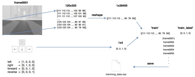
One advantage of using neural network is that once the network is trained, it only needs to load trained parameters afterwards, thus prediction can be very fast. Only lower half of the input image is used for training and prediction purposes. There are 38,400 (320×120) nodes in the input layer and 32 nodes in the hidden layer. The number of nodes in the hidden layer is chosen fairly arbitrary. There are four nodes in the output layer where each node corresponds to the steering control instructions: left, right, forward and reverse respectively (though reverse is not used anywhere in this project, it’s still included in the output layer).
One advantage of using neural network is that once the network is trained, it only needs to load trained parameters afterwards, thus prediction can be very fast. Only lower half of the input image is used for training and prediction purposes. There are 38,400 (320×120) nodes in the input layer and 32 nodes in the hidden layer. The number of nodes in the hidden layer is chosen fairly arbitrary. There are four nodes in the output layer where each node corresponds to the steering control instructions: left, right, forward and reverse respectively (though reverse is not used anywhere in this project, it’s still included in the output layer).

Below shows the training data collection process. First each frame is cropped and converted to a numpy array. Then the train image is paired with train label (human input). Finally, all paired image data and labels are saved into a npz file. The neural network is trained in OpenCV using back propagation method. Once training is done, weights are saved into a xml file. To generate predictions, the same neural network is constructed and loaded with the trained xml file.
Object Detection
This project adapted the shape-based approach and used Haar feature-based cascade classifiers for object detection. Since each object requires its own classifier and follows the same process in training and detection, this project only focused on stop sign and traffic light detection.
This project adapted the shape-based approach and used Haar feature-based cascade classifiers for object detection. Since each object requires its own classifier and follows the same process in training and detection, this project only focused on stop sign and traffic light detection.
OpenCV provides a trainer as well as detector. Positive samples (contain target object) were acquired using a cell phone, and were cropped that only desired object is visible. Negative samples (without target object), on the other hand, were collected randomly. In particular, traffic light positive samples contains equal number of red traffic lights and green traffic light. The same negative sample dataset was used for both stop sign and traffic light training. Below shows some positive and negative samples used in this project.


To recognize different states of the traffic light(red, green), some image processing is needed beyond detection. Flowchart below summarizes the traffic light recognition process.

Firstly, trained cascade classifier is used to detect traffic light. The bounding box is considered as a region of interest (ROI). Secondly, Gaussian blur is applied inside the ROI to reduce noises. Thirdly, find the brightest point in the ROI. Finally, red or green states are determined simply based on the position of the brightest spot in the ROI.
Distance Measurement
Raspberry Pi can only support one pi camera module. Using two USB web cameras will bring extra weight to the RC car and also seems unpractical. Therefore, monocular vision method is chosen.
Raspberry Pi can only support one pi camera module. Using two USB web cameras will bring extra weight to the RC car and also seems unpractical. Therefore, monocular vision method is chosen.
This project adapted a geometry model of detecting distance to an object using monocular vision method proposed by Chu, Ji, Guo, Li and Wang (2004).

P is a point on the target object; d is the distance from optical center to the point P. Based on the geometry relationship above, formula (1) shows how to calculate the distance d. In the formula (1), f is the focal length of the camera; ∂ is camera tilt angle; h is optical center height; (x0, y0) refers to the intersection point of image plane and optical axis; (x, y) refers to projection of point P on the image plane. Suppose O1 (u0,v0) is the camera coordinate of intersection point of optical axis and image plane, also suppose the physical dimension of a pixel corresponding to x-axis and y-axis on the image plane are dx and dy. Then:

v is the camera coordinates on y-axis and can be returned from the object detection process. All other parameters are camera’s intrinsic parameters that can be retrieved from camera matrix.
v is the camera coordinates on y-axis and can be returned from the object detection process. All other parameters are camera’s intrinsic parameters that can be retrieved from camera matrix.
OpenCV provides functions for camera calibration. Camera matrix for the 5MP pi camera is returned after calibration. Ideally, a_x and a_y have the same value. Variance of these two values will result in non-square pixels in the image. The matrix below indicates that the fixed focal length lens on pi camera provides a reasonably good result in handling distortion aspect. Here is an interesting article discussing the focal length of pi camera with stock lens and its equivalent to 35mm camera .
 The matrix returns values in pixels and h is measured in centimeters. By applying formula (3), the physical distance d is calculated in centimeters.
The matrix returns values in pixels and h is measured in centimeters. By applying formula (3), the physical distance d is calculated in centimeters.RC Car Control Unit
The RC car used in this project has an on/off switch type controller. When a button is pressed, the resistance between the relevant chip pin and ground is zero. Thus, an Arduino board is used to simulate button-press actions. Four Arduino pins are chosen to connect four chip pins on the controller, corresponding to forward, reverse, left and right actions respectively. Arduino pins sending LOW signal indicates grounding the chip pins of the controller; on the other hand sending HIGH signal indicates the resistance between chip pins and ground remain unchanged. The Arduino is connected to the computer via USB. The computer outputs commands to Arduino using serial interface, and then the Arduino reads the commands and writes out LOW or HIGH signals, simulating button-press actions to drive the RC car.
Results
Prediction on the testing samples returns an accuracy of 85% compared to the accuracy of 96% that the training samples returns. In actual driving situation, predictions are generated about 10 times a second (streaming rate roughly 10 frames/s).
Haar features by nature are rotation sensitive. In this project, however, rotation is not a concern as both the stop sign and the traffic light are fixed objects, which is also a general case in real world environment.


For distance measurement aspect, the ultrasonic sensor is only used to determine the distance to an obstacle in front of the RC car and provides accurate results when taking proper sensing angle and surface condition into considerations. On the other hand, Pi camera provides “good enough” measurement results. In fact, as long as we know the corresponding number to the actual distance, we know when to stop the RC car. Experimental results of detecting distance using pi camera are shown as below:

In this project, the accuracy of distance measurement using monocular vision approach could be influenced by the following factors: (1) errors in actual values measurement, (2) object bounding box variations in detecting process, (3) errors in camera calibration process, (4) nonlinear relationship between distance and camera coordinate: the further the distance, the more rapid change of camera coordinate, thus the greater the error.
Overall, the RC car could successfully navigate on the track with the ability to avoid front collision, and respond to stop sign and traffic light accordingly.
(Nguon: Zheng Wang blog)
Xe Tự Hành Sử Dụng OpenCV và deep learning (TiengAnh)
 Reviewed by Jacky
on
tháng 10 28, 2017
Rating:
Reviewed by Jacky
on
tháng 10 28, 2017
Rating:
Reviewed by Jacky
on
tháng 10 28, 2017
Rating:


Cho em hỏi ad đã làm cái này chưa ạ
Trả lờiXóa